Auto-leveling
Auto-leveling feature is the ability to probe user-defined areas to detect curved surfaces in your material. This is especially useful for engraving metal surfaces with V-shaped cutters where any deviation in the Z-direction will result in wider or narrower traces. Eg for isolation milling PCBs where warpage would result in broken traces.
How does it work?
Ultimate CNC using G38.2 will take Z values in different positions of XY (this we will name Grid Probe) and it will be stored in memory to process it.
The intermediate values of Z values are obtained via bilinear interpolation between the four nearest points. All G-code commands (like G00 or G01) whose length exceeds the Grid Probe are split up into sections smaller. It means the software will modify your original G-code program.
G-Codes supported by Auto-leveling feature:
- G00, G01 linear motion
- G02, G03 arc motion
- G04 dwell
- G20, G21 units
- G90, G91 distance mode
- S spindle speed
- M-codes
There are some G-codes unsupported in some scenarios, then if you use in your G-code, verify carefully the G-code autogenerated:
- G28 and G30
- G81 and G82
Configuration

Z up
This parameter defines the Z-axis position which is high enough to safely travel the X and Y axis with no risk of a tool collision.
Offset for Grid Probe
Add offset for grid probe in your G-code program units (mm or inches). This number must be greater than 0. We recommend using 1mm or 2mm. As you can see, Ultimate CNC automatically detects your piece, and then knows the limits for taking probe points, these limits are called the "bounding box" of your piece, then this "offset" parameter is added to the bounding box, for taking points of z-probe.
Fast Z Probe and Slow Z Probe
The G38.2 command will move an axis at a specified speed and stop once contact has been made between the Ground and the SEL pin on the CNC Shield (Arduino pin A5).
Slow: G91; G01 Z1; G38.2 Z-15 F10; G90 The command G38.2 Z-15 F10 will move the Z-Axis a distance of -15 mm slowly, at a speed of 10 mm a minute until contact is made to the ground.
Fast: G91; G38.2 Z-15 F100; G90 The command G38.2 Z-15 F100 will move the Z-Axis a distance of -15 mm slowly, at a speed of 100 mm a minute until contact is made to the ground.
Start auto-leveling procedure
To start 'Auto-leveling' click on the icon:
![]()
Then will appears Auto-leveling screen:

The auto-leveling screen is enabled only when you are connected to the Grbl board, and you have loaded some G-code program. To start auto-leveling procedure click on ' ① Start Probe ' button.
When finish probing your board, you can repeat some probe points or continue clicking on ' ② Autoleveling ' button.
Make sure you connect the GND wire to the bit of the router and the A5 pin wire to the probing piece. - ① Start Probe
- Start Z probing data on 'Grid Probe'
- ② Auto-leveling
- Modify your G-code program to use the new Z positions.
- Grid
- Show / hide grid probe.
- Probe
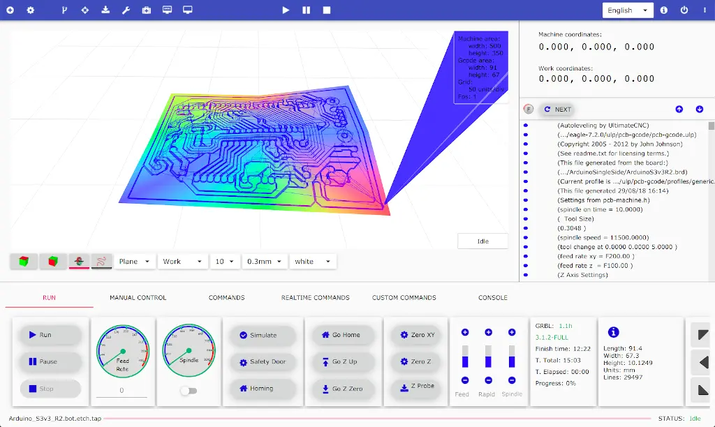
- Show obtained surface from Z probe data. The Blue color shows the maximum values of Z, Red is the minimum value, and Green is the medium value.
- Auto-leveling
- Enable / disable autoleveling.
The Z probe data can be loaded and saved as files using '① load' and '② save'.
Verify the new G-code generated
There are a lot of CAM programs than can generate G-code, and it can generate a lot of different scenarios. For this reason, Ultimate CNC has implemented an internal G-code processor to understand your original G-code. This way, the software can safely modify your G-code with the news Z values. However, Ultimate CNC gives you some tools to verify that the conversion is correctly done:
See the "Probe" plane
This plane shows you the new Z value when the original G-code was Z = 0, therefore you can verify that all new Z values have been processed correctly.
- The red color means the location where the Z has a lower value.
- The blue color means the location where the Z has the highest value.
- The green color indicates the location where the Z has an intermediate value between the red and blue Z values.

See the lines colors in the 3D Viewer.
All motion commands (G2, G3, ...) are converted to G00 and G01. You can see with G00 color "green" and G01 with color "pink".
Simulate the G-code.
It doesn't generate any motion in your CNC machine. If some value is missing, Grbl throw error.
