STL to G-code.
STL (STereoLithography) is a computer file format that defines the geometry of 3D objects, excluding information such as color, textures, or physical properties that other CAD formats do.
It was created by the company 3D Systems, conceived for use in the rapid prototyping industry and computer-aided manufacturing systems.
The STL format specifies both ASCII and BINARY representations, Ultimate CNC accepts ASCII and BINARY format, but ASCII is recommended nowadays.
Ultimate CNC extracts the contour shapes from your STL file and generates the G-code to process on your CNC machine with Grbl. This software does not process STL or generate G-code like the amazing (and expensive) Aspire vectric software can do. Check out the samples in this document to see what kind of outline shapes in your STL, Ultimate CNC will be able to generate G-Code.
Good free software to generate STL files is Sketchup, available directly from your browser Web:
Check this video to see how is converted a STL file from Sketchup to Ultimate CNC:
The following conversion, STL to G-code, are performed using the release, 3.2.4.
STL to G-code is useful to create panels for example. 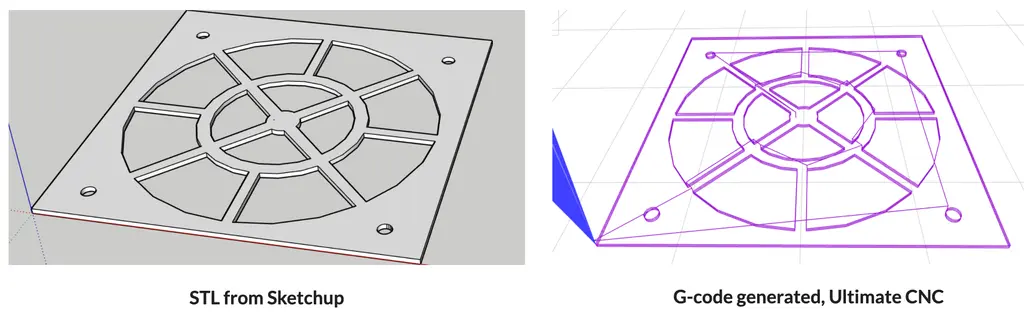
Converting STL to G-code:
![]()
When you open your STL file, a new screen appears with all the information you need to fill in to generate the G-code:
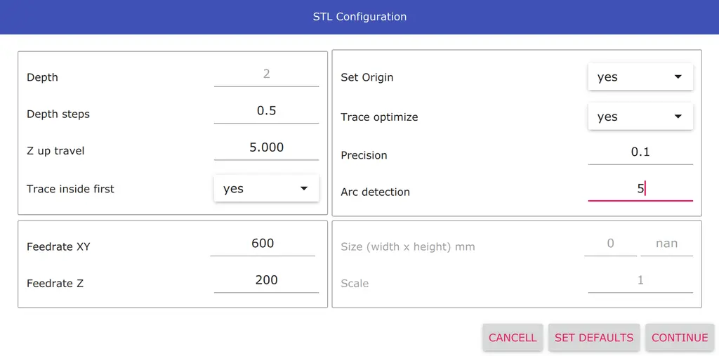
- Depth steps
- Depth for each step, it will end in full depth.
- Z up travel
- Z axis position when your cnc machine is moving to mill.
- Set Origin
- If you turn it off, Ultimate CNC will use the coordinates from your STL file. Otherwise, the coordinates of your file translate near of piece.
- Trace inside first
- Ultimate CNC will attempt to mill internal shapes and then external shapes. Enable by default.
- Trace optimize
- Ultimate CNC will try to find the best path to mill your part. Enable by default.
- Precision
- Before generating the G-code, the Ultimate CNC checks the distance between the points, and if it is too small, these points will be removed. It is necessary so as not to fill up the Grbl planner buffer. Minimum recommended 0.1/0.2 or greater, this value depends largely on the feed rate used. This value is in mm, real distances between points.
- Arc detection
- Ultimate CNC tries to discover circles on your image and will use to generate the G-code. This value is scaled to %. You can disable this functionality by setting a value of 0. The recommended value is 5%, but it is just a recommendation, the correct value has relation directly with the radius of circles that you want to detect and the quality/resolution of the image that you want to convert.
On the next screen you will be abe to choose:
- Shapes options
- You can select some shape detected and remove it or remove everything except the shape that you selected.
- Bouding box
- You can add a bounding box. It is a rectangular border that fully encloses your image.
- Milling
- The tool compensation can be selected: inline, inside, outside. It is an offset of the shape detected to compensate for the diameter of your tool.